Common Intelligence
Public Configurations
Context
Principles
The following describes the implementation of common intelligence on the LDU.
Cameras perform intelligent analysis using its own algorithm, and report alarms and snapshots to the HWT-IVS1800. The HWT-IVS1800 stores and manages alarms and displays alarms on the client. Figure 4-75 shows the process.

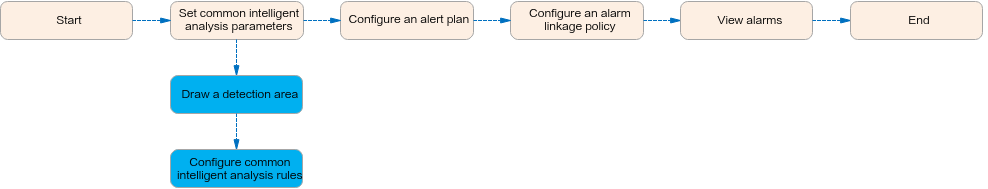
Configuration Process
Common intelligence can be configured on the LDU or in the camera web system.
This section describes only the configuration process on the LDU. For details about the configuration in the camera web system, see the product documentation of the corresponding camera.
Scenario Description
Table 4-66 describes the requirements for implementing common intelligence of cameras.
Application Limitations
- For details about the data retention period and clearance rules, see Data Clearance Rules.
- To configure intelligent analysis for cameras on the iClient S100, the camera version must be 9.0.0 or later.
Setting Global Parameters (Based on Cameras)
Prerequisites
- Cameras have been configured to synchronize time with the HWT-IVS1800. This function is enabled by default. For details, see Configuring Time Synchronization from a Camera to the HWT-IVS1800.
Procedure
- Log in to the LDU as the admin user. (
 Logging In to the LDU)
 - Disable the behavior analysis function.
- Click
 in the upper left corner.
 - Choose Intelligent Application > Camera Intelligence > Behavior Analysis > Global Configuration.
- Select a camera and toggle off Enable Global Behavior Analysis Configuration.
- Click
Related Feature Operations
Common intelligence includes the following features:
Motion Detection
Feature Description
Definition
An alarm is generated when an object moves within the specified detection area of the camera.
Customer Benefits
The system performs automatic detection and will generate an alarm to notify the security personnel of exceptions. In this case, the security personnel do not need to keep eyes on video images, improving detection efficiency and reducing labor costs.
Application Scenario
This feature is used to detect objects moving within the specified detection area of the camera, for example, in an exhibition hall.
Requirements
NE |
Version Requirement |
License Requirement |
Function |
|---|---|---|---|
HWT-IVS1800-D/HWT-IVS1800-E |
9.0.0 and later versions |
N/A |
Handles motion detection alarms. |
SDC |
8.0.0 and later versions |
N/A |
Motion detection |
Application Limitations
You are advised not to use this function in a single-color environment with frequent light or scene changes.
Feature Configuration (Based on Cameras)
Scenario Description
Table 4-67 describes the support for this feature in different client scenarios.
Client |
Feature Support |
Reference |
|---|---|---|
LDU |
Supported |
For details, see Procedure (on the LDU). |
Camera web system |
Supported |
Complete the configuration by referring to the product documentation of cameras. |
iClient S100 |
Supported |
For details, see Procedure (on the iClient S100). |
Prerequisites
- You have set the parameters listed in Public Configurations.
- You have configured alarm linkage on the iClient S100. For details, see Configuring Alarm Linkage.
Procedure (on the LDU)
To view the configuration guide video, you can click  in the upper left corner on the Configuration tab page, and scan the QR code.
- Log in to the LDU as the admin user. ( Logging In to the LDU)
- Click
 in the upper left corner.
 - Choose Intelligent Application > Camera Intelligence > Common Intelligence > Motion Detection.
- Configure a motion detection area, as shown in Figure 4-77.
Table 4-68 describes the key parameters and buttons.
Table 4-68 Parameter/Button descriptionType
Parameter
Description
Detection switch

Button for enabling or disabling the detection function.
Detection area drawing
Add
Button for adding a detection area.
A maximum of four detection areas are supported.
Delete
Button for deleting customized detection areas one by one.
Delete All
Button for deleting all detection areas.
Configuration
Sensitivity
Detection sensitivity.
The value ranges from 1 to 5. A larger value indicates higher sensitivity.
Alarm Interval (s)
Interval at which the system checks for motions. If motions are detected, an alarm is reported.
If an object is always moving, only one alarm is reported at each interval.
Sound And Light Alarm
Audio switch/Twinkle switch
Indicates whether to produce audible alarms (playing audio files) or visual alarms (blinking light) when an alarm is triggered.
Audio Output
Audio file to be played when an alarm is triggered.
- You can directly use this function when an intelligent IR/white-light camera with intercom is used.
- To use this function when a camera other than the intelligent IR/white-light camera with intercom is used, you need to set audio parameters for the camera and connect the camera to an external audio output device.
Frequency
Number of times for playing an audio file when an alarm is triggered.
Twinkle Freq
Frequency at which the light blinks when an alarm is triggered. You can set this parameter to Low frequency, Medium frequency, or High frequency as required.
Currently, the visual alarm (blinking light) function is available only for intelligent IR/white-light cameras with intercom. You need to set light-related parameters.
Twinkle Time(s)
Period in which the light blinks when an alarm is triggered.

The minimum length of a selected area is 50 pixels by default, and the total length is 480 pixels. If the distance from the start position of a selected area to the right border of the video image is less than the minimum length, the area cannot be selected.
- Configure an alert plan, as shown in Figure 4-78.
Table 4-69 describes the key parameters and buttons.
Table 4-69 Parameter/Button descriptionParameter/Button
Description
Add
Button for adding an alert plan. A maximum of eight alert plans are supported.
Delete All
Button for deleting all alert plans.

Button for enabling or disabling an alert plan. If you toggle on Status, the alert plan takes effect.
Day
Date on which an alert plan is executed.
The default value is Every Day.
Mode
Mode in which an alert plan is executed.
- Weekly
- One-off
- Configure an alarm linkage policy, as shown in Figure 4-79.
Table 4-70 describes the key parameters and buttons.
Table 4-70 Parameter/Button descriptionType
Parameter
Description
Common Linkage
Display ID
Indicates whether to display the status icon of the camera that triggers an alarm on the live video viewing page. This function is used to notify users of an alarm generated by the current camera.
Full-Screen Alarm
Indicates whether to display alarms in full screen mode.
After this function is enabled, if a camera triggers an alarm and the live video viewing page is displayed on the LDU, the live video of the camera is played in full screen mode for 5s.
CAUTION:If other alarms are generated when the live video is played in full-screen mode, the full-screen alarm function is not triggered.
Send Email
- Indicates whether to send email notifications. After this function is enabled, the system sends an email to the configured email recipient when a service alarm is generated.
- You can click
 to customize the alarm email recipient and email body.
The email address for sending service alarms needs to be customized on the OMU portal.
For details about how to set the email address for sending service alarms, see How Do I Configure Connection to the SMTP Server?.
Recording
Channel
Camera to be linked to record video when an alarm is triggered.
Duration(s)
Customized recording duration. The value ranges from 5 to 3600, in seconds. You are advised to set this parameter to a value greater than or equal to 60 (default).
Triggered Snapshot
Channel
Camera to be linked to take snapshots when an alarm is triggered.
NOTE:If both snapshot taking and email sending are configured for alarm linkage, you can obtain both the alarm-triggered snapshots and the snapshots sent in the email.
Stop Recording
Channel
Camera to be linked to stop video recording when an alarm is triggered.
I/O Alarm
Channel ID
Alarm reporting channel.
Duration(s)
Customized alarm linkage duration.
The value ranges from 1 to 3600, in seconds.
NOTE:If the specified alarm linkage duration is different from the I/O alarm output duration configured in How Do I Connect Cables and Configure Alarm Input and Output Ports?, the shorter alarm duration is used.
For example, if the I/O alarm output duration is set to 20s and the alarm linkage duration is set to 30s, the actual alarm output duration is 20s.
Invoke Preset Position
Channel
Camera to be linked. When a service alarm is generated, the linked camera rotates to the specified preset position.
Before enabling preset position linkage, ensure that a preset position has been configured for the camera to be linked. For details about how to configure a preset position, see Feature Configuration.
Device
Name of the camera that is linked to a preset position.
Position
Preset position linked to the camera.


Procedure (on the iClient S100)
- On the iClient S100 home page, choose Maintenance Management > Smart Configuration.
- Click a camera connected to a device and choose .
- Toggle on Enable Motion Detection, draw a detection area, and set related parameters.
- Set parameters in the Parameter Settings area. Table 4-71 describes the parameters.
Table 4-71 Parameter description
Parameter
Description
Alarm Detection Interval(s)
Interval at which the camera checks for object motion. If motion is detected, the camera reports an alarm.
If an object is always moving, only one alarm is reported at each interval.
Sensitivity
Motion detection sensitivity. A larger value indicates higher sensitivity. If this parameter is set to a larger value, more slight motions can be detected.
- Set audible and visual alarm parameters. Table 4-72 describes the parameters.
Table 4-72 Audible and visual alarm parameters
Parameter
Description
Requirement on the Camera
Enable audio alarms
Indicates whether to produce audible alarms (play audio files) when an alarm is triggered.
- You can directly use this function when an intelligent IR/white-light camera with intercom is used.
- To use this function when a camera other than the intelligent IR/white-light camera with intercom is used, you need to set audio parameters for the camera and connect the camera to an external audio output device.
Audio file
Audio file to be played when an alarm is triggered.
To import an audio file to the iClient S100, choose Maintenance Management > Video Device > Device List on the home page, double-click the required camera that is connected to a device, and add an audio file on the Audio Channel tab page.
Playback times
Number of times for playing an audio file when an alarm is triggered.
Enable light flashing alarm
Indicates whether to produce visual alarms (blinking lights) when an alarm is triggered.
Currently, these functions are available when an intelligent IR/white-light camera with intercom is used. You need to set light-related parameters.
White light illuminator
Frequency at which the light blinks when an alarm is triggered. You can set this parameter to Low, Middle, High, or Steady on as required.
Flash duration (s)
Period in which the light blinks when an alarm is triggered.
- Set area parameters, as shown in Figure 4-80. Table 4-73 describes the parameters.
Table 4-73 Area settings
Parameter
Description
+ Area
Button for adding a detection area. A maximum of four detection areas can be configured for analyzing a type of behavior. A maximum of 10 detection areas can be configured for analyzing all types of behavior.
You can select and drag the detection area or change its shape and size.
Delete
Button for deleting a selected detection area.
- Set plan parameters. Table 4-74 describes the parameters.
When the iClient S100 and a device are in different time zones, the time set in the Plan Settings area refers to the device time.
- Set parameters in the Parameter Settings area. Table 4-71 describes the parameters.
- Click Save.

Feature Verification
Viewing Alarms (on the LDU)
- Log in to the LDU as the admin user. ( Logging In to the LDU)
- View alarms on the LDU.
- Viewing real-time alarms
- Right-click on the desktop and choose Live > Alarm List.
- Click
 and select the type of alarms to be viewed, as shown in Figure 4-81.
- Click an alarm card in the alarm list to view the alarm in full screen mode, as shown in Figure 4-82.
- By default, the alarm-triggered video is 10s long (5s before and 5s after the alarm time).
- If you click
 , the alarm list on the left stops refreshing the latest alarms. If you click
  again, the system refreshes all new alarms generated after the alarm refresh stops.
- View historical alarms.
- Right-click on the desktop and choose Retrieval.
- Choose Event Retrieval.
- View alarms, as shown in Figure 4-83.
You can click the Browsing Status icon to switch the alarm browsing mode. Alarms in the alarm center can be browsed in card or list mode.
- Viewing real-time alarms


Viewing Alarms (on the iClient S100)
For details about how to view the latest or historical alarms, see Viewing Alarms (on the iClient S100).
Lens Blocking Detection
Feature Description
Definition
After lens blocking detection is configured, an alarm will be generated promptly when the lens is blocked.
Customer Benefits
This feature improves the camera O&M efficiency, reduces manual check costs, and ensures the video quality.
Application Scenario
This feature is applicable to scenarios that have high requirements on video quality. It is mainly used in outdoor scenarios where the camera lens may be blocked by surroundings.
Requirements
NE |
Version Requirement |
License Requirement |
Function |
|---|---|---|---|
HWT-IVS1800-D/HWT-IVS1800-E |
9.0.0 and later versions |
N/A |
Handles lens blocking alarms. |
SDC |
8.0.0 and later versions |
N/A |
Supports lens blocking detection. |
Application Limitations
You are advised not to use this function in a single-color environment with frequent light or scene changes.
Feature Configuration (Based on Cameras)
Scenario Description
Table 4-75 describes the support for this feature in different client scenarios.
Client |
Feature Support |
Reference |
|---|---|---|
LDU |
Supported |
For details, see Procedure (on the LDU). |
Camera web system |
Supported |
Complete the configuration by referring to the product documentation of cameras. |
iClient S100 |
Supported |
For details, see Procedure (on the iClient S100). |
Procedure (on the LDU)
To view the configuration guide video, you can click in the upper left corner on the Configuration tab page, and scan the QR code.
- Log in to the LDU as the admin user. ( Logging In to the LDU)
- Click
 in the upper left corner.
 - Choose Intelligent Application > Camera Intelligence > Common Intelligence > Lens Blocking.
- Configure the lens blocking detection area, as shown in Figure 4-84.
Table 4-76 describes the parameters.
Table 4-76 Parameter descriptionType
Parameter
Description
-

Button for enabling or disabling the detection function.
Configuration
Sensitivity
Detection sensitivity. There are five sensitivity levels ranging from 1 (the lowest level) to 5 (the highest level). With higher sensitivity, the camera can generate alarms when the lens is blocked by an object with a smaller size and brighter luminance.
Alarm Interval (s)
Interval at which the system checks for new lens blocking alarms.
Sound And Light Alarm
Audio switch/Twinkle switch
Indicates whether to produce audible alarms (playing audio files) or visual alarms (blinking light) when an alarm is triggered.
Audio Output
Audio file to be played when an alarm is triggered.
- You can directly use this function when an intelligent IR/white-light camera with intercom is used.
- To use this function when a camera other than the intelligent IR/white-light camera with intercom is used, you need to set audio parameters for the camera and connect the camera to an external audio output device.
Frequency
Number of times for playing an audio file when an alarm is triggered.
Twinkle Freq
Frequency at which the light blinks when an alarm is triggered. You can set this parameter to Low frequency, Medium frequency, or High frequency as required.
Currently, the visual alarm (blinking light) function is available only for intelligent IR/white-light cameras with intercom. You need to set light-related parameters.
Twinkle Time(s)
Period in which the light blinks when an alarm is triggered.
- Configure an alert plan, as shown in Figure 4-85.
Table 4-77 describes the key parameters and buttons.
Table 4-77 Parameter/Button descriptionParameter/Button
Description
Add
Button for adding an alert plan. A maximum of eight alert plans are supported.
Delete All
Button for deleting all alert plans.
Button for enabling or disabling an alert plan. If you toggle on Status, the alert plan takes effect.
Day
Date on which an alert plan is executed.
The default value is Every Day.
Mode
Mode in which an alert plan is executed.
- Weekly
- One-off
- Configure an alarm linkage policy, as shown in Figure 4-86.
Table 4-78 describes the key parameters and buttons.
Table 4-78 Parameter/Button descriptionType
Parameter
Description
Common Linkage
Display ID
Indicates whether to display the status icon of the camera that triggers an alarm on the live video viewing page. This function is used to notify users of an alarm generated by the current camera.
Full-Screen Alarm
Indicates whether to display alarms in full screen mode.
After this function is enabled, if a camera triggers an alarm and the live video viewing page is displayed on the LDU, the live video of the camera is played in full screen mode for 5s.
CAUTION:If other alarms are generated when the live video is played in full-screen mode, the full-screen alarm function is not triggered.
Send Email
- Indicates whether to send email notifications. After this function is enabled, the system sends an email to the configured email recipient when a service alarm is generated.
- You can click to customize the alarm email recipient and email body.
The email address for sending service alarms needs to be customized on the OMU portal.
For details about how to set the email address for sending service alarms, see How Do I Configure Connection to the SMTP Server?.
Recording
Channel
Camera to be linked to record video when an alarm is triggered.
Duration(s)
Customized recording duration. The value ranges from 5 to 3600, in seconds. You are advised to set this parameter to a value greater than or equal to 60 (default).
Triggered Snapshot
Channel
Camera to be linked to take snapshots when an alarm is triggered.
NOTE:If both snapshot taking and email sending are configured for alarm linkage, you can obtain both the alarm-triggered snapshots and the snapshots sent in the email.
Stop Recording
Channel
Camera to be linked to stop video recording when an alarm is triggered.
I/O Alarm
Channel ID
Alarm reporting channel.
Duration(s)
Customized alarm linkage duration.
The value ranges from 1 to 3600, in seconds.
NOTE:If the specified alarm linkage duration is different from the I/O alarm output duration configured in How Do I Connect Cables and Configure Alarm Input and Output Ports?, the shorter alarm duration is used.
For example, if the I/O alarm output duration is set to 20s and the alarm linkage duration is set to 30s, the actual alarm output duration is 20s.
Invoke Preset Position
Channel
Camera to be linked. When a service alarm is generated, the linked camera rotates to the specified preset position.
Before enabling preset position linkage, ensure that a preset position has been configured for the camera to be linked. For details about how to configure a preset position, see Feature Configuration.
Device
Name of the camera that is linked to a preset position.
Position
Preset position linked to the camera.

Procedure (on the iClient S100)
- On the iClient S100 home page, choose Maintenance Management > Smart Configuration.
- Click a camera connected to a device and choose .
- Toggle on Enable Video Occlusion and set related parameters.
- Set parameters in the Parameter Settings area. Table 4-79 describes the parameters.
Table 4-79 Parameter description
Parameter
Description
Alarm Detection Interval(s)
Interval at which the camera checks for video occlusion. If video occlusion is detected, the camera reports an alarm.
If an object is always occluded, only one alarm is reported at each interval.
Sensitivity
Motion detection sensitivity. A larger value indicates higher sensitivity. With higher sensitivity, the camera can generate alarms when the lens is blocked by an object with a smaller size and brighter luminance.
- Set audible and visual alarm parameters. Table 4-80 describes the parameters.
Table 4-80 Audible and visual alarm parameters
Parameter
Description
Requirement on the Camera
Enable audio alarms
Indicates whether to produce audible alarms (play audio files) when an alarm is triggered.
- You can directly use this function when an intelligent IR/white-light camera with intercom is used.
- To use this function when a camera other than the intelligent IR/white-light camera with intercom is used, you need to set audio parameters for the camera and connect the camera to an external audio output device.
Audio file
Audio file to be played when an alarm is triggered.
To import an audio file to the iClient S100, choose Maintenance Management > Video Device > Device List on the home page, double-click the required camera that is connected to a device, and add an audio file on the Audio Channel tab page.
Playback times
Number of times for playing an audio file when an alarm is triggered.
Enable light flashing alarm
Indicates whether to produce visual alarms (blinking lights) when an alarm is triggered.
Currently, these functions are available when an intelligent IR/white-light camera with intercom is used. You need to set light-related parameters.
White light illuminator
Frequency at which the light blinks when an alarm is triggered. You can set this parameter to Low, Middle, High, or Steady on as required.
Flash duration (s)
Period in which the light blinks when an alarm is triggered.
- Set plan parameters. Table 4-81 describes the parameters.
When the iClient S100 and a device are in different time zones, the time set in the Plan Settings area refers to the device time.
- Set parameters in the Parameter Settings area. Table 4-79 describes the parameters.
- Click Save.
Feature Verification
Viewing Alarms (on the LDU)
- Log in to the LDU as the admin user. ( Logging In to the LDU)
- View alarms on the LDU.
- Viewing real-time alarms
- Right-click on the desktop and choose Live > Alarm List.
- Click and select the type of alarms to be viewed, as shown in Figure 4-87.
- Click an alarm card in the alarm list to view the alarm in full screen mode, as shown in Figure 4-88.
- By default, the alarm-triggered video is 10s long (5s before and 5s after the alarm time).
- If you click , the alarm list on the left stops refreshing the latest alarms. If you click again, the system refreshes all new alarms generated after the alarm refresh stops.
- View historical alarms.
- Right-click on the desktop and choose Retrieval.
- Choose Event Retrieval.
- View alarms, as shown in Figure 4-89.
You can click the Browsing Status icon to switch the alarm browsing mode. Alarms in the alarm center can be browsed in card or list mode.
- Viewing real-time alarms
Viewing Alarms (on the iClient S100)
For details about how to view the latest or historical alarms, see Viewing Alarms (on the iClient S100).
Scene Change Detection
Feature Description
Definition
After scene change detection is configured, an alarm will be generated in a timely manner when the observation scene changes due to manual movement of the camera or other reasons.
Customer Benefits
This feature improves the camera O&M efficiency, reduces manual check costs, and ensures the video quality.
Application Scenario
This feature is applicable to scenarios that have high requirements on video quality. It is mainly used in outdoor scenarios where the camera may move or rotate due to natural surroundings and fail to focus on the detected target.
Requirements
NE |
Version Requirement |
License Requirement |
Function |
|---|---|---|---|
HWT-IVS1800-D/HWT-IVS1800-E |
11.1.0 and later versions |
N/A |
Handles scene change alarms. |
SDC |
8.0.0 and later versions |
N/A |
Supports scene change detection. |
Application Limitations
- You are advised not to use this function in a single-color environment with frequent light or scene changes.
- This feature is supported only for cameras connected through the HWSDK protocol.
Feature Configuration (Based on Cameras)
Scenario Description
Table 4-82 describes the support for this feature in different client scenarios.
Prerequisites
You have set the parameters listed in Public Configurations.
Procedure
To view the configuration guide video, you can click in the upper left corner on the Configuration tab page, and scan the QR code.
- Log in to the LDU as the admin user. ( Logging In to the LDU)
- Click
 in the upper left corner.
 - Choose Intelligent Application > Camera Intelligence > Common Intelligence > Scene Change Detection.
- Configure scene change detection, as shown in Figure 4-90.
Table 4-83 describes the key parameters.
Table 4-83 Parameter descriptionParameter
Description

Button for enabling or disabling the detection function.
Sensitivity
Detection sensitivity. The value is an integer ranging from 1 to 100. A larger value indicates a higher probability to trigger alarms.
NOTE:- In outdoor bus stations or crossroads, traffic is heavy and the scene changes greatly. To prevent false alarms from being reported, it is recommended that the sensitivity be set to a value less than 20.
- For indoor scenarios that are relatively stable, it is recommended that the sensitivity be set to 50.
Alarm Interval(s)
Interval at which the system checks for new scene change alarms.
- Configure an alert plan, as shown in Figure 4-91.
Table 4-84 describes the key parameters and buttons.
Table 4-84 Parameter/Button descriptionParameter/Button
Description
Add
Button for adding an alert plan. A maximum of eight alert plans are supported.
Delete All
Button for deleting all alert plans.
Button for enabling or disabling an alert plan. If you toggle on Status, the alert plan takes effect.
Day
Date on which an alert plan is executed.
The default value is Every Day.
Mode
Mode in which an alert plan is executed.
- Weekly
- One-off
- Configure an alarm linkage policy, as shown in Figure 4-92.
Table 4-85 describes the key parameters and buttons.
Table 4-85 Parameter/Button descriptionType
Parameter
Description
Common Linkage
Display ID
Indicates whether to display the status icon of the camera that triggers an alarm on the live video viewing page. This function is used to notify users of an alarm generated by the current camera.
Full-Screen Alarm
Indicates whether to display alarms in full screen mode.
After this function is enabled, if a camera triggers an alarm and the live video viewing page is displayed on the LDU, the live video of the camera is played in full screen mode for 5s.
CAUTION:If other alarms are generated when the live video is played in full-screen mode, the full-screen alarm function is not triggered.
Send Email
- Indicates whether to send email notifications. After this function is enabled, the system sends an email to the configured email recipient when a service alarm is generated.
- You can click to customize the alarm email recipient and email body.
The email address for sending service alarms needs to be customized on the OMU portal.
For details about how to set the email address for sending service alarms, see How Do I Configure Connection to the SMTP Server?.
Recording
Channel
Camera to be linked to record video when an alarm is triggered.
Duration(s)
Customized recording duration. The value ranges from 5 to 3600, in seconds. You are advised to set this parameter to a value greater than or equal to 60 (default).
Triggered Snapshot
Channel
Camera to be linked to take snapshots when an alarm is triggered.
NOTE:If both snapshot taking and email sending are configured for alarm linkage, you can obtain both the alarm-triggered snapshots and the snapshots sent in the email.
Stop Recording
Channel
Camera to be linked to stop video recording when an alarm is triggered.
I/O Alarm
Channel ID
Alarm reporting channel.
Duration(s)
Customized alarm linkage duration.
The value ranges from 1 to 3600, in seconds.
NOTE:If the specified alarm linkage duration is different from the I/O alarm output duration configured in How Do I Connect Cables and Configure Alarm Input and Output Ports?, the shorter alarm duration is used.
For example, if the I/O alarm output duration is set to 20s and the alarm linkage duration is set to 30s, the actual alarm output duration is 20s.
Invoke Preset Position
Channel
Camera to be linked. When a service alarm is generated, the linked camera rotates to the specified preset position.
Before enabling preset position linkage, ensure that a preset position has been configured for the camera to be linked. For details about how to configure a preset position, see Feature Configuration.
Device
Name of the camera that is linked to a preset position.
Position
Preset position linked to the camera.

Feature Verification
Procedure
- Log in to the LDU as the admin user. ( Logging In to the LDU)
- View alarms.
- Viewing real-time alarms
- Right-click on the desktop and choose Live > Alarm List.
- Click and select the type of alarms to be viewed, as shown in Figure 4-93.
- Click an alarm card in the alarm list to view the alarm in full screen mode, as shown in Figure 4-94.
- By default, the alarm-triggered video is 10s long (5s before and 5s after the alarm time).
- If you click , the alarm list on the left stops refreshing the latest alarms. If you click again, the system refreshes all new alarms generated after the alarm refresh stops.
- Viewing historical alarms
- Right-click on the desktop and choose Retrieval.
- Choose Event Retrieval.
- View alarms, as shown in Figure 4-95.
You can click the Browsing Status icon to switch the alarm browsing mode. Alarms in the alarm center can be browsed in card or list mode.
- Viewing real-time alarms
Defocus Detection
Feature Description
Definition
If the focal length of a camera is inappropriate, the images may be unclear. Users can configure defocus detection to generate alarms promptly when the camera is out of focus.
Customer Benefits
This feature improves the camera O&M efficiency, reduces manual check costs, and ensures the video quality.
Application Scenario
This feature is applicable to scenarios that have high requirements on video quality. It is mainly used in outdoor scenarios where the camera may move or rotate due to natural surroundings and fail to focus on the detected target.
Requirements
NE |
Version Requirement |
License Requirement |
Function |
|---|---|---|---|
HWT-IVS1800-D/HWT-IVS1800-E |
11.1.0 and later versions |
N/A |
Handles defocus alarms. |
SDC |
8.0.0 and later versions |
N/A |
Detects defocus. |
Application Limitations
- You are advised not to use this function in a single-color environment with frequent light or scene changes.
- This feature is supported only for cameras connected through the HWSDK protocol.
Feature Configuration (Based on Cameras)
Scenario Description
Table 4-86 describes the support for this feature in different client scenarios.
Prerequisites
You have set the parameters listed in Public Configurations.
Procedure
To view the configuration guide video, you can click in the upper left corner on the Configuration tab page, and scan the QR code.
- Log in to the LDU as the admin user. ( Logging In to the LDU)
- Click in the upper left corner.
- Choose Intelligent Application > Camera Intelligence > Common Intelligence > Defocus Detection.
- Configure the defocus detection alarm, as shown in Figure 4-96.
Table 4-87 describes the key parameters and buttons.
Table 4-87 Parameter/Button descriptionType
Parameter/Button
Description
Detection switch

Button for enabling or disabling the detection function.
Alarm Settings
Sensitivity
Detection sensitivity. The value ranges from 1 to 100. A larger value indicates higher sensitivity.
Alarm Interval(s)
Interval at which alarms are checked, in seconds.
- Configure an alert plan, as shown in Figure 4-97.
Table 4-88 describes the key parameters and buttons.
Table 4-88 Parameter/Button descriptionParameter/Button
Description
Add
Button for adding an alert plan. A maximum of eight alert plans are supported.
Delete All
Button for deleting all alert plans.
Button for enabling or disabling an alert plan. If you toggle on Status, the alert plan takes effect.
Day
Date on which an alert plan is executed.
The default value is Every Day.
Mode
Mode in which an alert plan is executed.
- Weekly
- One-off
- Configure an alarm linkage policy, as shown in Figure 4-98.
Table 4-89 describes the key parameters and buttons.
Table 4-89 Parameter/Button descriptionType
Parameter
Description
Common Linkage
Display ID
Indicates whether to display the status icon of the camera that triggers an alarm on the live video viewing page. This function is used to notify users of an alarm generated by the current camera.
Full-Screen Alarm
Indicates whether to display alarms in full screen mode.
After this function is enabled, if a camera triggers an alarm and the live video viewing page is displayed on the LDU, the live video of the camera is played in full screen mode for 5s.
CAUTION:If other alarms are generated when the live video is played in full-screen mode, the full-screen alarm function is not triggered.
Send Email
- Indicates whether to send email notifications. After this function is enabled, the system sends an email to the configured email recipient when a service alarm is generated.
- You can click to customize the alarm email recipient and email body.
The email address for sending service alarms needs to be customized on the OMU portal.
For details about how to set the email address for sending service alarms, see How Do I Configure Connection to the SMTP Server?.
Recording
Channel
Camera to be linked to record video when an alarm is triggered.
Duration(s)
Customized recording duration. The value ranges from 5 to 3600, in seconds. You are advised to set this parameter to a value greater than or equal to 60 (default).
Triggered Snapshot
Channel
Camera to be linked to take snapshots when an alarm is triggered.
NOTE:If both snapshot taking and email sending are configured for alarm linkage, you can obtain both the alarm-triggered snapshots and the snapshots sent in the email.
Stop Recording
Channel
Camera to be linked to stop video recording when an alarm is triggered.
I/O Alarm
Channel ID
Alarm reporting channel.
Duration(s)
Customized alarm linkage duration.
The value ranges from 1 to 3600, in seconds.
NOTE:If the specified alarm linkage duration is different from the I/O alarm output duration configured in How Do I Connect Cables and Configure Alarm Input and Output Ports?, the shorter alarm duration is used.
For example, if the I/O alarm output duration is set to 20s and the alarm linkage duration is set to 30s, the actual alarm output duration is 20s.
Invoke Preset Position
Channel
Camera to be linked. When a service alarm is generated, the linked camera rotates to the specified preset position.
Before enabling preset position linkage, ensure that a preset position has been configured for the camera to be linked. For details about how to configure a preset position, see Feature Configuration.
Device
Name of the camera that is linked to a preset position.
Position
Preset position linked to the camera.

Feature Verification
Procedure
- Log in to the LDU as the admin user. ( Logging In to the LDU)
- View alarms.
- Viewing real-time alarms
- Right-click on the desktop and choose Live > Alarm List.
- Click and select the type of alarms to be viewed, as shown in Figure 4-99.
- Click an alarm card in the alarm list to view the alarm in full screen mode, as shown in Figure 4-100.
- By default, the alarm-triggered video is 10s long (5s before and 5s after the alarm time).
- If you click , the alarm list on the left stops refreshing the latest alarms. If you click again, the system refreshes all new alarms generated after the alarm refresh stops.
- Viewing historical alarms
- Right-click on the desktop and choose Retrieval.
- Choose Event Retrieval.
- View alarms, as shown in Figure 4-101.
You can click the Browsing Status icon to switch the alarm browsing mode. Alarms in the alarm center can be browsed in card or list mode.
- Viewing real-time alarms
Video Quality Detection
Feature Description
Definition
With the video quality diagnosis function, cameras can automatically detect problems such as image freezing, color cast, and static noise in the video, identifying faulty cameras.
The following table describes the video quality problems that can be detected with this function.
Exception |
Description |
|---|---|
Image freezing |
The video image stays at a static frame for a long period of time. |
Gain imbalance |
The video image is too bright or too dark. You are advised not to enable this function in scenarios with lights or low illuminance. |
Color cast |
A tint of a particular color, usually unwanted, affects the whole, or portion, of a photographic image evenly. Enable the color cast diagnosis when there are high requirements on the video image quality. You are advised not to enable this function in scenarios with low illuminance or bright colors. |
Static noise |
A snow-like random pattern is superimposed on the video image due to electromagnetic noises. You are advised not to enable this function in scenarios with lights or low illuminance. |
Stripe noise |
A stripe-like random pattern is superimposed on the video image due to electromagnetic noises. You are advised not to use this function in scenes with horizontal or vertical bars (such as equipment rooms or crosswalks). |
Image shaking |
Irregular distortion or movement occurs on the video image. You are advised not to use this function in densely-populated areas, scenes with lights, or low illuminance scenarios. |
Customer Benefits
This feature improves camera O&M efficiency and ensures video quality.
Application Scenario
This feature is applicable to scenarios that have high requirements on video quality. It is mainly used in outdoor scenarios where video quality problems may occur due to natural surroundings.
Requirements
NE |
Version Requirement |
License Requirement |
Function |
|---|---|---|---|
HWT-IVS1800-D/HWT-IVS1800-E |
11.1.0 and later versions |
N/A |
Handles video quality diagnosis alarms. |
SDC |
8.0.0 and later versions |
N/A |
Supports video quality diagnosis. |
Application Limitations
- You are advised not to use this function in a single-color environment with frequent light or scene changes.
- This feature is supported only for cameras connected through the HWSDK protocol.
Feature Configuration (Based on Cameras)
Scenario Description
Table 4-90 describes the support for this feature in different client scenarios.
Procedure
To view the configuration guide video, you can click in the upper left corner on the Configuration tab page, and scan the QR code.
- Log in to the LDU as the admin user. ( Logging In to the LDU)
- Click
 in the upper left corner to access the main menu.
 - Choose Intelligent Application > Camera Intelligence > Common Intelligence > Video Quality Diagnosis.
- Configure video quality diagnosis alarms, as shown in Figure 4-102.
Table 4-91 describes the key parameters.
Table 4-91 Parameter descriptionParameter
Application Scenario
Image Freezing
Check whether the live video image remains static for a long time.
Gain Imbalance
Check whether the live video image is too bright or too dark.
You are advised not to use this function when intense light or dim light exists in the live video view.
Color Cast
Check whether a color cast occurs on the live video image.
- You are advised to enable this function if you want to ensure high-quality live video images.
- You are advised not to enable this function in low-illumination or bright-color live video.
Static Noise
Check whether noise interference exists on the live video image.
You are advised not to use this function when intense light or dim light exists in the live video view.
Stripe Noise
Check whether stripe interference occurs on the live video image.
You are advised not to use this function in environments (for example, equipment room and zebra crossing) with stripes.
Image Shaking
Check whether video image shaking occurs.
You are advised not to use this function in scenes with a large flow of people or vehicles.
- Configure an alert plan, as shown in Figure 4-103.
Table 4-92 describes the key parameters and buttons.
Table 4-92 Parameter/Button descriptionParameter/Button
Description
Add
Button for adding an alert plan. A maximum of eight alert plans are supported.
Delete All
Button for deleting all alert plans.
Button for enabling or disabling an alert plan. If you toggle on Status, the alert plan takes effect.
Day
Date on which an alert plan is executed.
The default value is Every Day.
Mode
Mode in which an alert plan is executed.
- Weekly
- One-off
- Configure an alarm linkage policy, as shown in Figure 4-104.
Table 4-93 describes the key parameters and buttons.
Table 4-93 Parameter/Button descriptionType
Parameter
Description
Common Linkage
Display ID
Indicates whether to display the status icon of the camera that triggers an alarm on the live video viewing page. This function is used to notify users of an alarm generated by the current camera.
Full-Screen Alarm
Indicates whether to display alarms in full screen mode.
After this function is enabled, if a camera triggers an alarm and the live video viewing page is displayed on the LDU, the live video of the camera is played in full screen mode for 5s.
CAUTION:If other alarms are generated when the live video is played in full-screen mode, the full-screen alarm function is not triggered.
Send Email
- Indicates whether to send email notifications. After this function is enabled, the system sends an email to the configured email recipient when a service alarm is generated.
- You can click to customize the alarm email recipient and email body.
The email address for sending service alarms needs to be customized on the OMU portal.
For details about how to set the email address for sending service alarms, see How Do I Configure Connection to the SMTP Server?.
Recording
Channel
Camera to be linked to record video when an alarm is triggered.
Duration(s)
Customized recording duration. The value ranges from 5 to 3600, in seconds. You are advised to set this parameter to a value greater than or equal to 60 (default).
Triggered Snapshot
Channel
Camera to be linked to take snapshots when an alarm is triggered.
NOTE:If both snapshot taking and email sending are configured for alarm linkage, you can obtain both the alarm-triggered snapshots and the snapshots sent in the email.
Stop Recording
Channel
Camera to be linked to stop video recording when an alarm is triggered.
I/O Alarm
Channel ID
Alarm reporting channel.
Duration(s)
Customized alarm linkage duration.
The value ranges from 1 to 3600, in seconds.
NOTE:If the specified alarm linkage duration is different from the I/O alarm output duration configured in How Do I Connect Cables and Configure Alarm Input and Output Ports?, the shorter alarm duration is used.
For example, if the I/O alarm output duration is set to 20s and the alarm linkage duration is set to 30s, the actual alarm output duration is 20s.
Invoke Preset Position
Channel
Camera to be linked. When a service alarm is generated, the linked camera rotates to the specified preset position.
Before enabling preset position linkage, ensure that a preset position has been configured for the camera to be linked. For details about how to configure a preset position, see Feature Configuration.
Device
Name of the camera that is linked to a preset position.
Position
Preset position linked to the camera.


Feature Verification
Procedure
- Log in to the LDU as the admin user. ( Logging In to the LDU)
- View alarms.
- Viewing real-time alarms
- Right-click on the desktop and choose Live > Alarm List.
- Click and select the type of alarms to be viewed, as shown in Figure 4-105.
- Click an alarm card in the alarm list to view the alarm in full screen mode, as shown in Figure 4-106.
- By default, the alarm-triggered video is 10s long (5s before and 5s after the alarm time).
- If you click , the alarm list on the left stops refreshing the latest alarms. If you click again, the system refreshes all new alarms generated after the alarm refresh stops.
- Viewing historical alarms
- Right-click on the desktop and choose Retrieval.
- Choose Event Retrieval.
- View alarms, as shown in Figure 4-107.
You can click the Browsing Status icon to switch the alarm browsing mode. Alarms in the alarm center can be browsed in card or list mode.
- Viewing real-time alarms
Audio Diagnosis
Audio Anomaly Detection
Feature Description
Definition
An alarm is generated when the microphone is disconnected from the camera.
Customer Benefits
This feature improves camera O&M efficiency, reducing the cost of manual check.
Application Scenario
For cameras with microphones, this feature is used to check whether the microphones function properly.
Application Limitations
This feature is supported only for cameras connected through the HWSDK protocol.
Feature Configuration (Based on Cameras)
Scenario Description
Table 4-94 describes the support for this feature in different client scenarios.
Prerequisites
You have set the parameters listed in Public Configurations.
Feature Verification
Procedure
- Log in to the LDU as the admin user. ( Logging In to the LDU)
- View alarms.
- Viewing real-time alarms
- Right-click on the desktop and choose Live > Alarm List.
- Click and select the type of alarms to be viewed, as shown in Figure 4-108.
- Click an alarm card in the alarm list to view the alarm in full screen mode, as shown in Figure 4-109.
- By default, the alarm-triggered video is 10s long (5s before and 5s after the alarm time).
- If you click , the alarm list on the left stops refreshing the latest alarms. If you click again, the system refreshes all new alarms generated after the alarm refresh stops.
- Viewing historical alarms
- Right-click on the desktop and choose Retrieval.
- Choose Event Retrieval.
- View alarms, as shown in Figure 4-110.
You can click the Browsing Status icon to switch the alarm browsing mode. Alarms in the alarm center can be browsed in card or list mode.
- Viewing real-time alarms
Sudden Volume Increase or Decrease Detection
Feature Description
Definition
When the camera detects abrupt sound changes, for example, screams, an alarm is automatically generated.
Customer Benefits
The system automatically detects and triggers alarms to remind security personnel. Security personnel do not need to focus on images, reducing time and labor costs.
Application Scenario
This feature is used to detect abnormal sounds in places such as school buildings, underground walkways, and parks.
Application Limitations
This feature is supported only for cameras connected through the HWSDK protocol.
Feature Configuration (Based on Cameras)
Scenario Description
Table 4-95 describes the support for this feature in different client scenarios.
Prerequisites
You have set the parameters listed in Public Configurations.
Feature Verification
Procedure
- Log in to the LDU as the admin user. ( Logging In to the LDU)
- View alarms.
- Viewing real-time alarms
- Right-click on the desktop and choose Live > Alarm List.
- Click and select the type of alarms to be viewed, as shown in Figure 4-111.
- Click an alarm card in the alarm list to view the alarm in full screen mode, as shown in Figure 4-112.
- By default, the alarm-triggered video is 10s long (5s before and 5s after the alarm time).
- If you click , the alarm list on the left stops refreshing the latest alarms. If you click again, the system refreshes all new alarms generated after the alarm refresh stops.
- Viewing historical alarms
- Right-click on the desktop and choose Retrieval.
- Choose Event Retrieval.
- View alarms, as shown in Figure 4-113.
You can click the Browsing Status icon to switch the alarm browsing mode. Alarms in the alarm center can be browsed in card or list mode.
- Viewing real-time alarms